
Programming
Tool Library Management
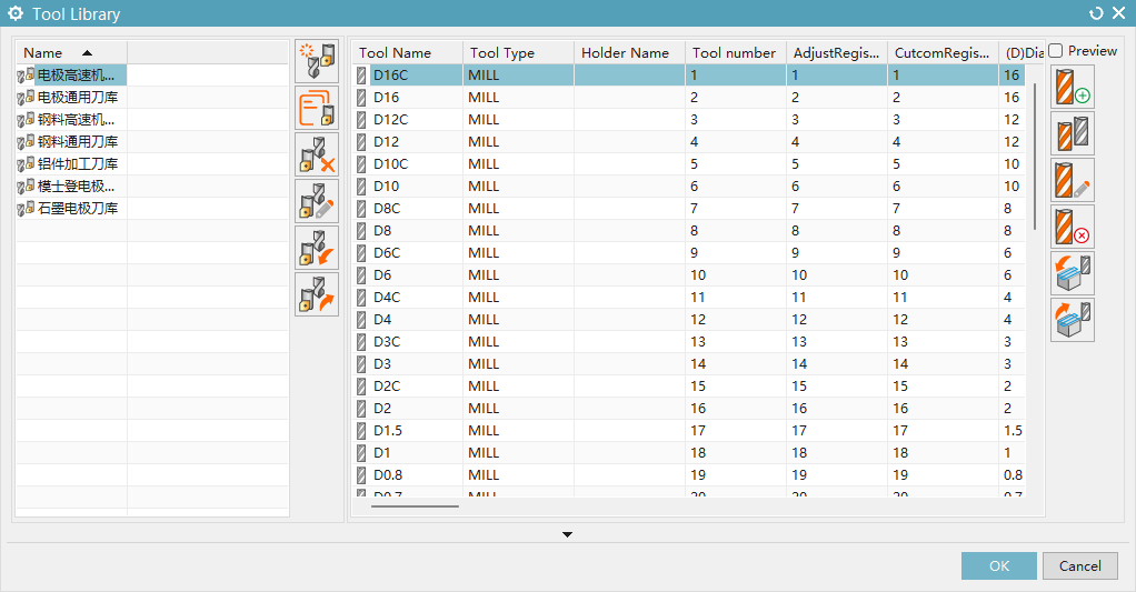 The Tool Library is used to centrally store and manage all tools. You can:
- Manage tool libraries: Use the buttons on the left to create new, copy, delete, or rename tool libraries
- Add tools: Select the tool category, enter the tool name, set tool dimensions, holder, tool holder, and cutting parameters, then click Save to add the tool to the tool library
- Preview: Select a tool and check Preview to view the tool's 3D model
- Edit tools: Modify tool category, dimensions, holder, tool holder, and cutting parameters
- Copy and delete tools
Cutting Parameters
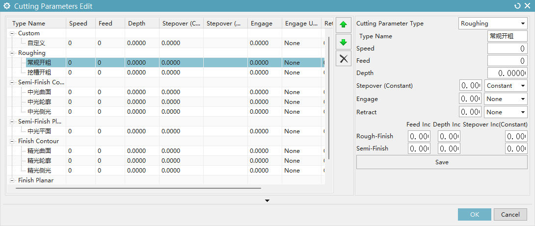
- Select the cutting parameter type
- Set spindle speed, feed rate, depth of cut, stepover, approach, and retract
- Multiple cutting conditions can be set
Machining Solution Management
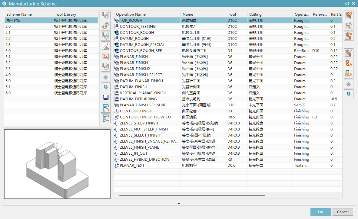
- Create, delete, copy, and rename solutions
- Set solution preview images
- Import and export solutions
- Add, copy, and delete operations, and adjust operation order
- Set tools, select cutting parameters to call from the tool library, and set reference tools
- Set operation groups (Roughing, Secondary Roughing, Reference, Finishing, Semi-finishing, Engraving) to determine operation processing methods
- Set strategies (Electrode solid body layer, All faces of the body, etc.) to determine operation processing scope
- Set operation parameters (Side stock, Bottom stock, Tolerance)
Programming
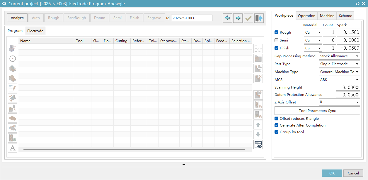
Workpiece and Electrode Analysis
- Rough electrode, Medium electrode, Finish electrode: Read spark gap from electrode properties; checking the option generates the corresponding option upon completing the electrode
- Spark method: Options include Negative Stock, Tool Offset, Tool Offset Negative Z
- Machine type: Standard machine / High-speed machine; together with Rough/Medium/Finish electrode materials, determines the initial tool library selected
- Machining coordinate system: Select the coordinate system as the geometry's coordinate system
- Top trimming scanning height: Set the scanning blank distance
- Reference surface protection stock: Set the check stock for reference surface protection; operations without check stock will be reflected in the cutting layer range depth
- Synchronize tool library parameters: After changing the tool library, update the cutting parameters in the current solution
- Ball nose tool offset synchronously reduces R angle: When checked, tool offset on ball nose tools reduces the lower radius while reducing the diameter; if insufficient, switches from tool offset to negative stock method
- Generate on completion: Whether to generate toolpaths when the Complete button is clicked
- Coloring for planar faces, vertical faces, steep faces, non-steep faces, reference faces, and reference face side faces
- Automatically read electrode properties (electrode ID, spark gap, etc.)
- Initialize MCS and workpiece geometry
Solution Management
- The central area of the programming window displays the current solution
- The right-side list displays the solutions created in the machining solution management
- Double-click a solution in the right-side list to replace the current solution
- When a current solution exists, double-click an operation in a solution from the right-side list to add that operation to the current solution
- In Settings, you can select an existing solution as the automatic solution
- Click the Automatic Solution button to load the automatic solution (it will not replace the current solution)
Operation Groups (Roughing, Secondary Roughing, Reference, Semi-finishing, Finishing, Engraving)
Operation groups are collections of similar operations. For example, the "Roughing" group contains all operations used for rough machining. Operation groups determine the processing method
In the preset configuration, select the solution to preset; operations will be automatically assigned based on the operation groups set in that solution
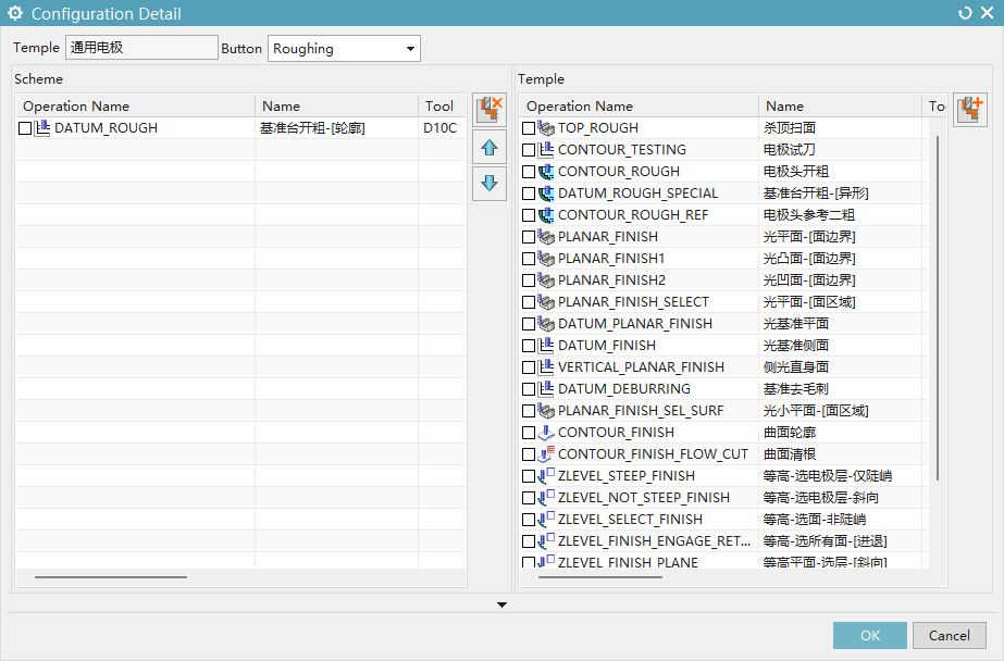
Clicking the operation group button will add the corresponding operation groups from the preset configuration solution to the current solution
Operation Management
- Copy, delete, and drag to reorder operations (multi-select supported); copy, delete, and drag to reorder operation group data
- Generate: Execute generation for selected operations to preview toolpaths
- New group: Create a new empty operation group
- Edit: Invoke NX's operation editing
- Select tool: Change the operation's tool and update cutting parameters; batch update supported. This function can be triggered by double-clicking the tool column of an operation, and double-clicking the tool column of an operation group to batch update all operations within the group
- Select reference tool: Change the operation's reference tool; batch update supported. This function can be triggered by double-clicking the reference tool column of an operation, and double-clicking the reference tool column of an operation group to batch update all operations within the group
- Move Up/Down: Move an operation up or down by one position. This method can only move operations within the same operation group
Right-Click Menu
- Edit, Copy, Delete, Generate, Select Tool, Select Reference Tool: Same as operation management
- Rename: Rename the operation
- Toggle generation status: Check/uncheck the ✓ mark before operations. Operations without the ✓ mark will not participate in generation when the Complete button is clicked
- Operation selection: In the sub-menu, you can select the operation to be added; after selection, the operation is added to the current solution from a template. Operations added this way require re-selecting a tool
- Column configuration: Adjust the columns displayed in the current solution and their order
- Expand All: Expand all operation groups
- Collapse All: Collapse all operation groups
Current Solution
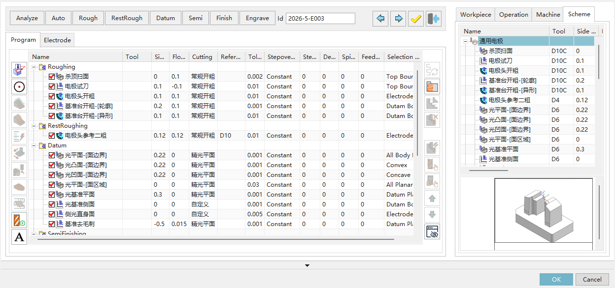
In the current solution list, you can edit operation parameters directly
- Selection: Both operations and operation groups support single-click selection and shift/ctrl multi-selection
- Single-click (operation): Side stock, bottom stock, tolerance, stepover, depth of cut, and feed rate can be modified by selecting an operation, clicking the corresponding column, and entering a new value
- Single-click (operation group): Side stock, bottom stock, tolerance, stepover, depth of cut, and feed rate can be modified by selecting an operation group, clicking the corresponding column, and entering a new value. This will modify the corresponding column for all operations within the group
- Cutting: Select from the dropdown; after changing, the stepover, depth of cut, and feed rate will be updated to the corresponding parameters set in the tool library
- Select strategy: Cannot be modified in the current solution
Auxiliary Functions
Dynamic Properties
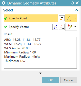
- Displays the coordinates, maximum radius, minimum radius, thickness, and groove width at the mouse cursor position
Dynamic Circle
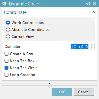
- Coordinate system: Create a dynamic circle using the work coordinate system, absolute coordinate system, or current coordinate system
- Diameter: Diameter of the dynamic circle or side length of the square
- Create: Creates a circle by default; checking Create Square allows creation of a square. Circle and square can be created simultaneously
- Save: Save the created geometry
- Loop creation: Can only be checked when any Save option is checked; allows continuous generation and saving of geometries
Surface Lifting
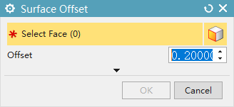
- Select faces: Select the faces to be protected
- Offset: Offset the selected faces by the offset value in the Z direction to generate sheets, which are then added to the operation's part to protect the faces
Set Area Faces
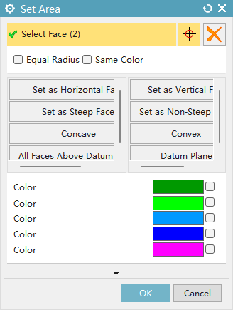
- Select faces: Manually select faces to specify cutting area or face boundaries
- Clear: Delete all faces from the face selector
- Same-radius fillets: When checked, selecting a fillet will simultaneously select all fillets with the same radius in the geometry
- Same-color faces: When checked, selecting a face will simultaneously select all faces of the same color
- Quick selection: Click buttons to add corresponding faces (horizontal faces, vertical faces, steep faces, non-steep faces, concave faces, convex faces, all faces above the reference face, reference plane) to the face selector
- Color face selection: Check the corresponding color to add faces of that color to the face selector
Set Cutting Layer
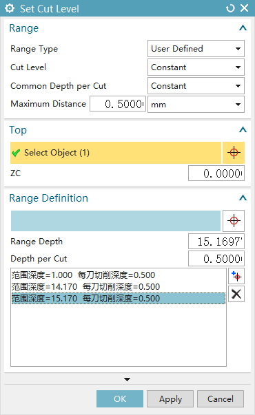
- Range type: User Defined, Automatic, Single Side, corresponding to the same-named range types in NX; switching will reset the cutting layer
- Cutting layer: Constant, Range Bottom Only, corresponding to the same-named cutting types in NX
- Common area cutting depth: Constant, Residual Height; Constant uses Maximum Distance control, Residual Height uses Maximum Residual Height control
- Maximum Distance / Maximum Residual Height: Enter a value, select a unit, and set the cutting depth
- Top: Select the top of the cutting layer, can be set by face selection or by ZC coordinate
- Range definition: Manage cutting ranges through the list; display specific layers by selecting them from the list; individual layer range depths can be adjusted independently
Set Cutting Direction
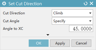
- This function is the same as NX's cutting direction function
Approach Point
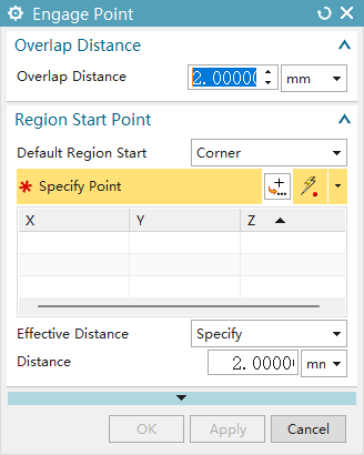
- This function is the same as NX's Non-Cutting Moves - Start/Drill Point function
Check Body
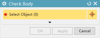
- Set the selected objects as the check body for the selected operation
Create Temporary Tool
- Same as Create Tool; creates a temporary tool that does not belong to any tool library
Engraving Settings
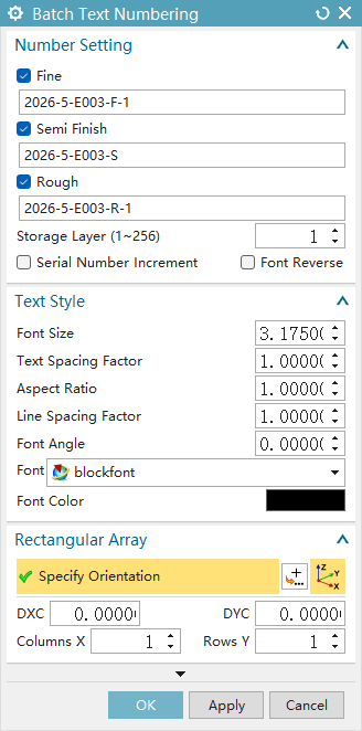
- Number settings: Check to determine whether to generate text; the text box determines the generated text content
- Storage layer: The layer where text is stored
- Serial number increment: Increment the engraving serial number
- Font reverse: Flip the font direction
- Text style: Determines font size, text spacing factor, aspect ratio, line spacing factor, font angle, font, and font color
- Rectangular array: Determines the coordinate position for engraving